方向性結合器の原理の解説。原文と訳を並べた。
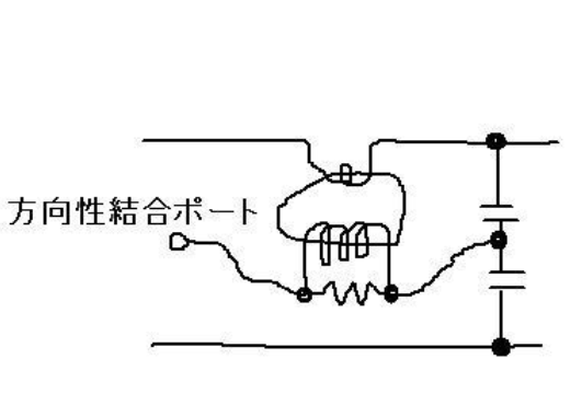
CM型方向性結合器と言われるものである。
■次の解説を翻訳する。
https://directional-coupler.com/tutorials/functional-principle-of-a-directional-coupler/
Functional principle of a directional coupler

Fig.1(図1)
In a simplified model we will describe the fundamentals of coaxial directional couplers with one coupling loop. The principle is essentially the same for most other directional couplers.
1つのカップリングループで同軸方向性結合器を、簡単なモデルで説明する。この原理は、ほとんどの方向性結合器で本質的に同じである。
Coaxial directional couplers use the fact, that the direction of the electric field (E-field) between inner and outer conductor is equal for the forward and the reverse wave. However, the magnetic field (H-field), with the direction around the inner conductor of the coaxial line has an opposite rotational direction for the forward and the reverse wave. We will exemplify this at a directional loop coupler corresponding to Fig. 1.
同軸方向性結合器は使う。内外間の間の電界の方向は、信号の進む向きにはよらない。しかし、内部導体による磁界の方向は信号の進む方向で異なる。これを図1に方法性ループ結合器で示す。
The radio frequency (rf) power flowing from the amplifier to the load results in a radial electric field from the inner conductor to the outer conductor (ground) and a circular magnetic field between inner and outer conductor.
RF信号のアンプから負荷へのパワーの流れは、内外導体間の電界と、磁界に現れる。
A small part of the electric field couples capacitively from the inner conductor to the coupling plate of the coupling loop. This leads to an rf voltage of this plate against ground and an rf current which flows over the electrically leading metallic spacers equally through the two 50 ohm resistors to ground. This voltage that arises due to the capacitive coupling of the forward wave is equal on both ports and positive. In the following we call this voltage +Vcap.
電界の小部分は、内部導体から結合ループの結合片間の静電容量を結び付ける。これは、GNDに対するこの小片の電圧を決め、電流は、2つの抵抗(50Ω)でGNDにつながれる。進む向きの信号の結合容量による電圧は、両方のポートで等しく正である。これを+Vcapと書く。
As already mentioned, the forward wave also gene rates a circular magnetic field, which is vertical and clockwise oriented to the direction of the propagation. This magnetic field is located around the inner conductor and is bound by the outer conductor. A small part of this magnetic field penetrates the coupling loop.
すでに言ったように、進む信号は磁界を発生させる。それは右まわりである。この磁界は内部導体と外部導体の間にできる。この磁界は結合ループをつらぬく。
The coupling loop, consisting of the coupling plate, the two metallic spacers, the two resistors and the ground between the resistors is building a closed circuit. The so-called magnetic flux through the coupling loop induces a current Iind in this closed loop. This current generates a positive voltage +Vind at port 1, flowing through the resistor at port 1.
結合片、2つの金属スペーサー、GNDにつながる抵抗で構成されるループは閉回路となる。磁束はこのループに電流を誘発する。このっ電流はポート1に正の電圧+Vindを派生させる。
After passing this resistor, the induced current Iind flows along the ground to the resistor at port 2. The direction of this current through the resistor at port 2 is opposite to the current through the resistor at port 1. This leads to a negative voltage –Vind at port 2, before the current flows back to the coupling plate.
この抵抗を通った後、ポート2の抵抗を流れる。このポート2の抵抗を通る電流の方向は、ポート1の抵抗を通る電流と逆である。これはポート2に負の電圧ーVindを発生させる。
If one can obtain by an appropriate geometry, that Vcap and Vind are equal in amplitude and phase, this will result in twice the voltage on port 1, adding V cap and V ind, while adding Vcap and –Vind on port 2 will lead to zero voltage. In this case the forward wave couples a part of the transported power to port 1 while nothing of it couples to port 2.
For the reverse wave with the same direction of the E-field but contrary direction of the H-field it is vice versa. Here the capacitive and inductive coupling adds on port 1 while they extinguish each other on port 2.
もし、適切な形で説明できるなら、VcapとVindが大きさ位相が同じなら、ポート1では2倍の電圧になり、ポート2では0になる。この場合、進む信号は、ポート1に伝送パワーの一部を結合させ、ポート2にはなにも結合しない。これと逆向きに進む信号では電界は同じ方向で、磁界は逆になる。静電容量と電磁誘導結合はポート1では足し合わされ、ポート2では互いを打ち消す。
On port 1 one only measures a proportional part of the forward wave and on port 2 only a proportional part of the reverse wave. Thus the directional coupler can separately measure the forward and reverse wave.
In practice you will never find ideal conditions as just described. If Vcap und Vind are not exactly equal, the forward wave will couple a small part of the forward power to port 2 as well. Similarly the reverse wave will couple a small part to port 1.
ポート1では進む信号のみに比例した値を測れ、ポート2では逆方向に進む信号のみに比例した値を測定できる。このため、方向性結合器は進む信号と、それとは逆に進む方向の信号をわけて測定できる。実際に???
もし、VcapとVindが正確に等しくないと、進む信号はポート2に結合する。同じように、逆方向に進む信号はポート1に結合する。
If for example the forward wave couples one thousandth of the transported power to port 1, the directional coupler has a coupling factor of –30 db. Consider further an example, where one measures –65 dB on port 2 (instead of ideally – infinity dB) because of a small diversity between capacitive and inductive coupling (even with an ideal matching of the main line without a reverse wave). In this case there is a difference in the coupling of port 1 and port 2 of 35 dB. This factor is called the directivity of a directional coupler, which is in this example 35 dB.
The directivity is a measure of how well capacitive and inductive coupling of a directional coupler are matched in amplitude and phase. We recommend a directivity of at least 30 dB, better 35 to 40 dB. After our explanations about the two voltages Vcap and Vind above, you can imagine that not only the geometry of the coupling loop but also the quality and equality of the two 50 ohm resistors have a strong influence on the directivity of the directional coupler.
To summarize, we have shown how a directional coupler works and specifically, how a perfect directional coupler is able to measure the forward and reverse wave separately. Additionally, we defined the parameter directivity of a directional coupler and its connection to a non-symmetric geometry.

■個別部品で構成した場合

図2 個別部品で構成した方向性結合器
■R&K社の資料から引用する
R & K D C S e r i e s 方向性結合器は高周波低損失の方向性結合器で、其の全体を分類すれば基本的に2種類の製品群で構成されております。 まず第一に、フェライト・トランス巻線(Transmission Line Ferrite Transformer)を応用した集中定数回路方式の、広帯域で低損失な方向性結合器です。 そして第二に広帯域ストリップラインを利用した分布定数回路方式、いわゆるCM結合に同様な、しかし超広帯域で低損失な方向性結合器です。 両者共に物理的詳細動作説明を行えば共に全く同様な電気回路であります。 R & K D C S e r i e s方向性結合器は、それぞれ個別に内部回路が明示されておりますが、其の基本的な回路説明は、相互に方向性のある『二つの結合接続した入出力線路』であり、IN⇒OUT接続は非常に低損失でありながらIN⇒FWD(進行波結合出力)が所定のレベルで結合しており、そしてOUT⇒REF(反射波結合出力)が所定のレベルで結合しています。 しかしIN⇒REF間と、
OUT⇒FWD間は全てが所定のアイソレーション値でアイソレーション(絶縁)されています。 これらの電気的接続された相互の接続間において『電気的な方向性』が得られる理由は、集中定数でも分布定数でも誘導M結合による電流分岐出力と電圧分岐出力が其々180度位相が違う事を利用して、進行波と反射波でマトリックス回路を組み方向性のあるモニター出力を得ています。 これらの製品群は主線路に出来るだけ影響を与えないで高周波信号を広帯域で平坦にサンプル抽出する、モニター出力回路として非常に利用されております。
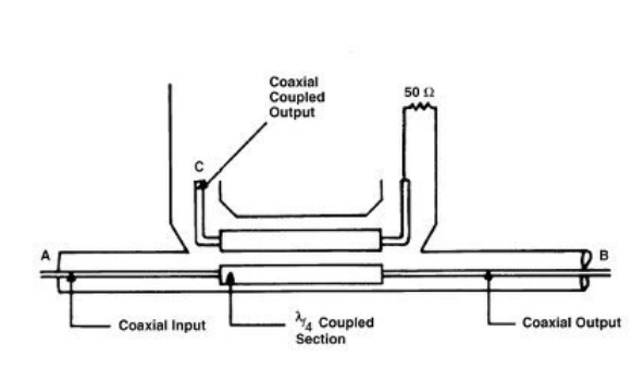
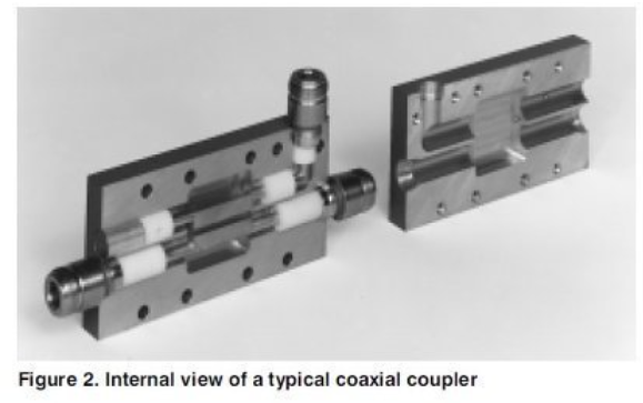
■λ/4、narda社の資料から
参考文献
http://kilyos.ee.bilkent.edu.tr/~microwave/programs/magnetic/dcoupler/theory.htm


線路を含めたIN インピーダンスは
Vs/Is=(cosh(jkl)*Rl + Z0*sinh(jkl))/(sinh(jkl)*Rl/Z0 + cosh(jkl))
=(cos(kl)*Rl+Z0*j*sin(kl))/(j*sin(kl)*Rl/Z0+cos(kl))
Z0^2/RL
参考
方向性結合器の原理|EMC村の民 (engineer-climb.com)
方向性結合器-その動作と応用.pdf (mrf.co.jp)
方向性結合器について | マイクロニクス (micronix-jp.com)
オシロスコープとスペアナの振幅の関係 | マイクロニクス (micronix-jp.com)
いまさら聞けないスペクトラムアナライザの基礎(2)RBW(分解能帯域幅)について | マイクロニクス (micronix-jp.com)
無線機設計におけるRF技術のすべて 無線機設計におけるRF技術のすべて